
RIGID SHAFTED
SCREW CONVEYOR
A robust positive-displacement conveyor in which a motor-driven central shaft with helical flights moves powders, granules and bul solids through a rigid U-trough or enclosed pipe casing.
HOW THE SYSTEM WORKS

FEED
A regulated upstream device loads the inlet.


FILL
Material occupies the selected trough loading.

ROTATE
The geared drive turns the central shaft.

ADVANCE
Helical flights push material axially.

TRANSFER
The casing contains material and dust.

DISCHARGE
Product falls through the outlet opening.
WHEN A RIGID SCREW CONVEYOR IS THE RIGHT CHOICE
PROCESS FIT
Dry to semi-fluid solids
Handles many free-flowing, sluggish or moderately abrasive materials.
Controlled horizontal transfer
Provides consistent movement between nearby process stages.
Dust containment
Covered troughs and pipe casings limit product loss and exposure.
KEY ADVANTAGES
Multiple process connections
U-trough designs can accept selected inlets and discharge points.
Positive displacement
Speed and flight geometry provide predictable volumetric transfer.
Automation ready
Drive current, speed, level and downstream permissives can connect to the PLC.
CONSTRUCTION & CONFIGURATION OPTIONS
CONSTRUCTION
Carbon steel, SS304 or SS316L product-contact construction
HOUSING
Covered U-trough or fully enclosed pipe-type casing
FLIGHT OPTIONS
Full, short, variable, ribbon, cut or cut-and-folded flights
CONFIGURATION
Horizontal or mild incline with one or multiple process connections
CLEANING
Removable covers, clean-out doors, dry clean or wash-compatible design
PROTECTION
Current overload, zero-speed, blockage and access safety interlocks
RIGID SHAFTED SCREW OPERATING CONCEPТ
Material is control-fed into the casing at a selected trough loading. A geared drive rotates the central shaft and helical flights, advancing product along the rigid housing before gravity discharge into the receiving equipment.
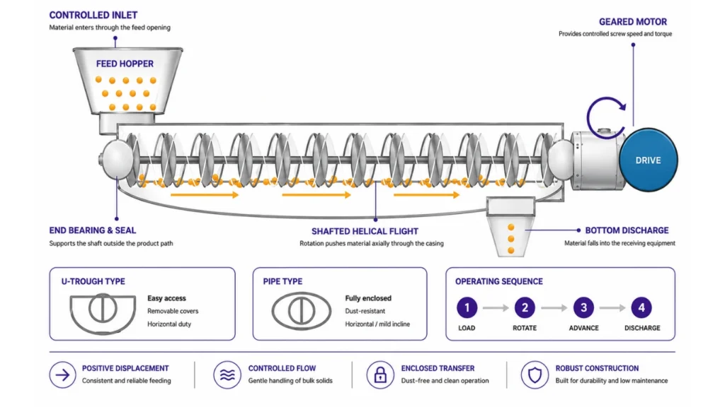
CONTROLLED OPERATING SEQUENCE
FEED
Requlate product into the inlet.
LOAD
Maintain selected trough fill.
ROTATE
Geared drive turns the shaft.
ADVANCЕ
Flights push product axially.
DISCHARGE
Release through the outlet.
CONTROL, PROTECTION & MAINTENANCE
Start-up permissive
Confirm downstream readiness and start the conveyor before upstream feed
Current monitoring
Rising motor current can indicate overfill, compaction, bearing drag or blockage.
Shaft protection
Correct loading, hanger spacing, speed and torque protect shafts and couplings.
Discharge confirmation
Downstream equipment readiness is interlocked with conveyor operation.
Access protection
Inspection covers and drive guards are interlocked where required.
Cleaning access
Removable trough covers and clean-out points support inspection and sanitation.
STANDARD CAPACITY & PRELIMINARY SIZING
Catalogue screening basis: free-flowing dry powder at 0.5 kg/L bulk density, standard full-pitch screw, horizontal duty and controlled inlet. Select the
permitted trough loading for the actual material before sizing.
|
MODEL
|
SCREW DIAMETER
|
STANDARD PITCH
|
MAX. GUIDE SPEED
|
CAPACITY @ 30% LOADING
|
CAPACITY @ 0.5 kg/L
|
DUTY CLASS
|
|---|---|---|---|---|---|---|
|
RS-100
|
100 mm
|
100 mm
|
135 rpm
|
1.6 m3/h
|
0.8 t/h
|
Compact
|
|
RS-150
|
150 mm
|
150 mm
|
120 rpm
|
5.1 m3/h
|
2.5 t/h
|
Light duty
|
|
RS-225
|
225 mm
|
225 mm
|
100 гpm
|
15.4 m3/h
|
7.7 t/h
|
General
|
|
RS-300
|
300 mm
|
300 mm
|
90 гpm
|
32.9 m3/h
|
16.4 t/h
|
Medium
|
|
RS-400
|
400 mm
|
400 mm
|
80 rpm
|
70.7 m3/h
|
35.3 t/h
|
Bulk
|
|
RS-450
|
450 mm
|
450 mm
|
75 rpm
|
95.6 m3/h
|
47.8 t/h
|
High duty
|
CAPACITY CALCULATION BASIS
TROUGH LOADING GUIDE
15% | 30% | 45%
Abrasive/sluggish | General | Light/free-flowing
MASS CAPACITY
Qm = Qv x bulk density / 1000
Qm in t/h; Qv in m3/h; density in kg/m3
WHAT CONTROLS THE FINAL SELECTION
Material behaviour
Flowability, fragility, abrasion, moisture and temperature.
Diameter & pitch
Screw diameter, standard or reduced pitch and usable cross-section.
Speed & drive
Required throughput, starting torque, VFD range and service factor.
Length & incline
Centre distance, angle, hanger bearings and discharge elevation.
Controlled loading
A regulated inlet maintains design trough loading and prevents overload.
Cleaning & safety
Cover access, clean-out method, guarding,
earthing and dust hazards.
FINAL ENGINEERING CHECK
Confirm material and capacity
Assign trough loading
Select diameter and pitch
Calculate speed, power and torque
Agree trial /FAT criteria
Need the Right RIGID SHAFTED SCREW CONVEYOR
for Your Process?
Our engineers will help you select, size and configure the ideal system for your application.
Download Product Brochure
Fill in your details below to download the brochure.