
TUBULAR DRAG-DISC
CONVEYOR
A fully enclosed mechanical conveyor in which polymer or stainless discs, fixed at regular intervals to a cable or chain, gently drag powders and granules through tubular pipework along horizontal, vertical and curved routes.
HOW THE SYSTEM WORKS

FEED
Material enters through a controlled loading station.


CAPTURE
Disc pockets collect product within the tube.

CONVEY
The cable or chain drags product through the closed line.

LIFT
The same circuit moves horizontally and vertically.

DISCHARGE
Product exits through the selected outlet.

RETURN
Empty discs circulate back to the loading point.
WHEN TUBULAR DRAG CONVEYING IS THE RIGHT CHOICE
PROCESS FIT
Route flexibility
One enclosed circuit can combine horizontal, vertical and curved sections.
Gentle transfer
Low conveying speed can limit attrition, segregation and product damage.
Dust containment
Closed tubes reduce product loss, operator exposure and housekeeping.
KEY ADVANTAGES
Compact installation
Useful where floor space is limited or equipment levels are
separated.
Single or multiple outlets
Discharge stations can be configured to suit the process
layout.
Automation ready
Drive, tension, blockage and route interlocks can connect to the plant PLC.
CONSTRUCTION & CONFIGURATION OPTIONS
TUBE MОС
SS304, SS316L or application-specific construction
DISC OPTIONS
Food-grade polymer, UHMWPE or stainless steel
CARRIER
Cable or chain selected for route, load and
temperature
ROUTING
Horizontal, vertical and large-radius curved sections
CLEANING
Dry clean-out, access sections, air purge or wash option
PROTECTION
Torque, motion, tension, blockage and access interlocks
TUBULAR DRAG-DISC OPERATING CONCEPТ
A continuous cable or chain carries evenly spaced discs through a closed tubular circuit. Product fills the spaces between discs, travels through the required route and is released at the discharge before the empty discs return.
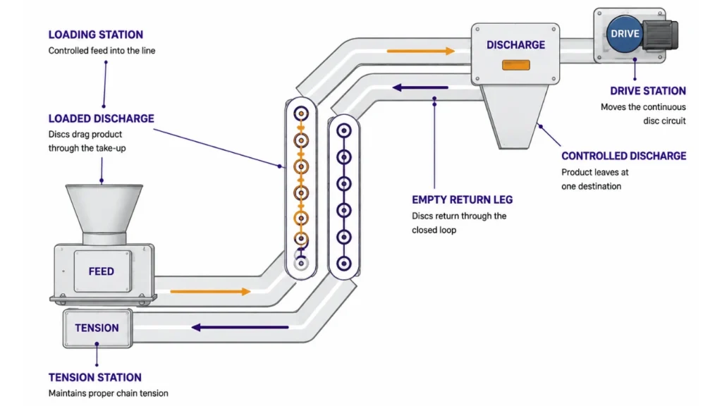
CONTROLLED OPERATING SEQUENCE
FEED
Meter material into the tube
CAPTURE
Fill spaces between discs.
CONVEY
Drag through the closed route.
LIFT
Move horizontally or vertically.
DISCHARGE
Release into the destination.
CONTROL, PROTECTION & MAINTENANCE
Start-up permissive
The drive starts before the upstream feeder and the line clears before stopping.
Torque monitoring
Overload or rising torque can indicate overfeeding, blockage or disc damage.
Carrier condition
Tension, motion and speed monitoring protect the cable or chain circuit.
Discharge confirmation
Outlet valve and downstream readiness are interlocked with material feed.
Access protection
Inspection covers and drive guards are interlocked where required.
Cleaning access
Quick-release sections and clean-out points support inspection and sanitation.
STANDARD CAPACITY & PRELIMINARY SIZING
Catalogue screening basis: free-flowing dry material at 0.5 kg/L bulk density, continuous duty, moderate route complexity and approximately 40-70% effective tube fill.
|
MODEL
|
TUBE SIZE
|
DISC PITCH
|
TYPICAL SPEED
|
VOLUMETRIC CAPACITY
|
CAPACITY @ 0.5 kg/L
|
ROUTE CLASS
|
|---|---|---|---|---|---|---|
|
TD-50
|
50 mm
|
50-80 mm
|
0.1-0.3 m/s
|
0.3-1.0 m3/h
|
0.15-0.5 t/h
|
Compact
|
|
TD-80
|
80 mm
|
70-110 mm
|
0.1-0.35 m/s
|
1-3 m3/h
|
0.5-1.5 t/h
|
Light duty
|
|
TD-100
|
100 mm
|
90-140 mm
|
0.12-0.4 m/s
|
2-5 m3/h
|
1-2.5 t/h
|
General
|
|
TD-125
|
125 mm
|
110-170 mm
|
0.12-0.45 m/s
|
4-10 m3/h
|
2-5 t/h
|
Medium
|
|
TD-150
|
150 mm
|
130-200 mm
|
0.15-0.5 m/s
|
7-18 m3/h
|
3.5-9 t/h
|
Bulk
|
|
TD-200
|
200 mm
|
170-260 mm
|
0.15-0.5 m/s
|
15-35 m3/h
|
7.5-17.5 t/h
|
High duty
|
CAPACITY CALCULATION BASIS
VOLUMETRIC CAPACITY
Qv = 3600 x Aeff x v x eta
Aeff in m2; v in m/s; eta is effective fill factor
MASS CAPACITY
Qm = Qv x rho / 1000
Qm in t/h; rho is bulk density in kg/m3
WHAT CONTROLS THE FINAL SELECTION
Material behaviour
Flowability, fragility, abrasion, moisture and temperature.
Tube & disc geometry
Clearance, disc diameter, pitch and usable cross-section.
Carrier selection
Cable or chain load, bend radius, tension and service life.
Route complexity
Length, vertical lift, bends and number of discharges.
Loading consistency
Metered feed prevents overfilling and high
drive torque.
Cleaning & safety
Access, cleanability, guarding, earthing and hazard controls.
FINAL ENGINEERING CHECK
Confirm material and capacity
Approve complete route drawing
Select tube, disc and carrier
Calculate drive and tension
Agree trial / FAT criteria
Need the Right TUBULAR DRAG-DISC CONVEYOR
for Your Process?
Our engineers will help you select, size and configure the ideal system for your application.
+918484041703
sales@adritis.com
www.adritis.com
Need the Right TUBULAR DRAG-DISC CONVEYOR
for Your Process?
Our engineers will help you select, size and configure the ideal system for your application.
Download Product Brochure
Fill in your details below to download the brochure.