
LEAN-PHASE
PNEUMATIC CONVEYING
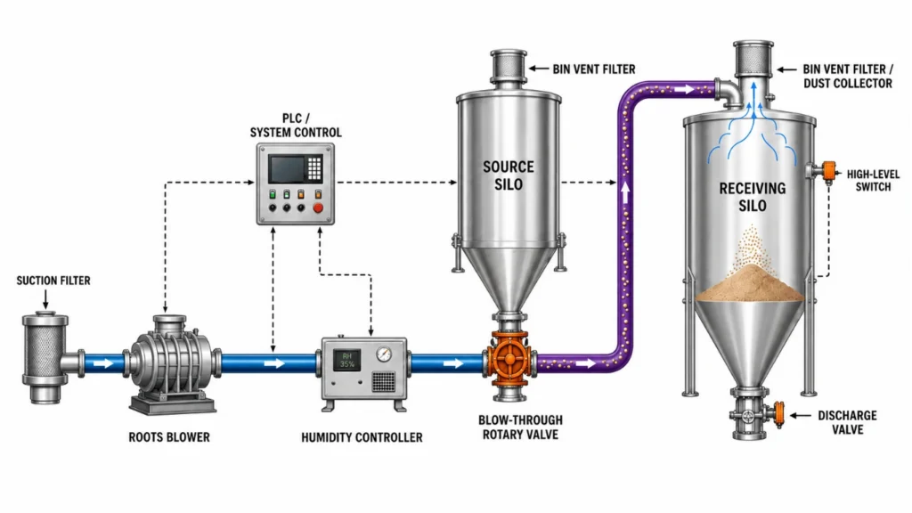
A continuous positive-pressure conveying system in which filtered, conditioned air carries powder or granules in suspension. A blow-through rotary valve meters product from the source silo into the air stream for transfer to the receiving silo or process equipment.
HOW THE SYSTEM WORKS

FILTER AIR
A suction filter protects the blower and conveying line.


GENERATE AIRFLOW
A Roots blower produces the required conveying-air volume.

CONDITION AIR
Humidity or dew point is controlled when the product requires it.

METER PRODUCT
A blow-through rotary valve feeds solids into the moving air stream.

SEPARATE & VENT
The receiver filter separates product while clean air is discharged.
WHEN LEAN PHASE IS THE RIGHT CHOICE
BEST SUITED FOR
Free-flowing products
Powders, grains and granules that can tolerate suspended-flow conveying.
Flexible routing
One source can feed multiple destinations through pressure-rated diverter valves.
Process integration
PLC sequencing, weighing, inert gas, batch tracking and interlocks can be integrated.
KEY ADVANTAGES
Capacity control
Rotary-valve speed and blower VFD can be coordinated with process demand.
Compact feed arrangement
The blow-through feeder fits directly below a source hopper or silo.
Clean automated transfer
Enclosed pipework, level logic, filter monitoring and permissives reduce manual handling.
TYPICAL APPLICATIONS
Silo-to-process transfer
Blender and reactor feeding
Packing-machine feed
Grains and free-flowing powders
Multi-destination distribution
Plant-wide continuous transfer
LEAN-PHASE OPERATING CONCEРТ
The airflow is established and conditioned before product is introduced. The rotary valve meters material into the same continuous line, and the receiving filter separates the solids from the conveying air.
CONTROLLED OPERATING SEQUENCE
FILTER INLET AIR
GENERATE AIRFLOW
CONTROL HUMIDITY
METER & CONVEY
SEPARATE/VENT
AUTOMATION, CONTROL & SAFETY
Blower permissive & VFD
Airflow is proven before the rotary valve starts; speed control maintains the selected velocity.
Humidity / dew-point control
Conditioned air protects hygroscopic material and supports repeatable powder behaviour.
Rotary-valve supervision
Feeder speed, rotation and isolation status are interlocked with blower and receiver availability.
Receiver-filter monitoring
Differential pressure and cleaning logic maintain airflow and protect conveying capacity.
Level and route permissives
High-level switches, destination selection and diverter feedback prevent overfilling or wrong routing.
Process safety
Earthing, relief, guarding and explosion-protection measures are engineered from the product hazard data.
STANDARD CAPACITY & PRELIMINARY PIPE SIZING
Catalogue screening basis: free-flowing powder at 0.5 kg/L bulk density, ambient condition, continuous blow-through feeding, 18-25 m/s line velocity and 3-6 kg product per kg of conveying air.
|
STANDARD MODEL
|
PIPE SIZE
|
LINE AIR VOLUME AT 18-25 m/s
|
INDICATIVE CAPACITY AT 0.5 kg/L
|
TYPICAL DUTY
|
|---|---|---|---|---|
|
LP-40
|
40 NB
|
1.4-1.9 m3/min
|
0.3-0.8 t/hr
|
Small / light-duty transfer
|
|
LP-50
|
50 NB
|
2.1-3.0 m3/min
|
0.5-1.3 t/hr
|
Light process feed
|
|
LP-65
|
65 NB
|
3.6-5.0 m3/min
|
0.8-2.2 t/hr
|
General process feed
|
|
LP-80
|
80 NB
|
5.4-7.5 m3/min
|
1.2-3.2 t/hr
|
Medium-duty transfer
|
|
LP-100
|
100 NB
|
8.5-11.8 m3/min
|
1.8-5.1 t/hr
|
Bulk transfer
|
|
LP-125
|
125 NB
|
13.3-18.4 m3/min
|
2.9-8.0 t/hr
|
High-duty transfer
|
SELECTING THE CONVEYING METHOD
|
CRITERION
|
PTS/VACUUM BATCH
|
DENSE PHASE
|
LEAN PHASE
|
|---|---|---|---|
|
Operating principle
|
Negative-pressure batch transfer
|
Positive-pressure plugs or dunes
|
Positive-pressure suspended flow
|
|
Primary feed device
|
Suction pickup and receiver
|
Pressure vessel/blow tank
|
Blow-through rotary valve
|
|
Typical velocity
|
Application-specific
|
About 4-12 m/s
|
About 15-35 m/s
|
|
Typical pressure
|
Vacuum
|
Commonly 1-6 bar(g)
|
Usually below 1 bar(g)
|
|
Best product fit
|
Contained batch transfer
|
Fragile, abrasive or segregating
|
Free-flowing, non-fragile product
|
|
Operating pattern
|
Batch/intermittent
|
Batch or near-continuous twin pot
|
Continuous
|
|
Main consideration
|
Receiver filter and headroom
|
Pressure-vessel complexity
|
Air use, wear and attrition
|
FINAL ENGINEERING CHECK
Confirm flow, moisture and explosibility data
Verify route, bends, elevations and destinations
Calculate pickup and terminal velocities
Size feeder, line, blower and receiver filter
Confirm relief, earthing and interlocks
Need the Right LEAN-PHASE PNEUMATIC CONVEYING
for Your Process?
Our engineers will help you select, size and configure the ideal system for your application.