
IBC/ INTERMEDIATE
BULK CONTAINER
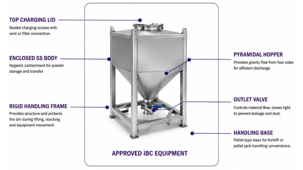
A reusable stainless-steel container for charging, storing, moving and discharging dry powders or granules as a closed batch. The square body, pyramidal hopper, protective frame and controlled outlet create a flexible interface between production stages.
HOW THE IBC WORKS

CHARGE
Fill through the top lid using a closed or dust-controlled connection.


CLOSE
Seal the lid, identify the batch and prove the outlet is closed.

STORE
Hold product in a protected, traceable intermediate container.

MOVE
Transfer the complete IBC between process stages using approved handling.

POSITION
Locate and secure the container above the downstream interface

DISCHARGE
Open the outlet valve and control gravity flow into the receiver.
APPLICATION FIT & PROCESS VALUE
RIGHT APPLICATION
Pharmaceutical and nutraceutical
Batch transfer of powders, excipients, granules and premixes with reduced open handling.
Food and specialty ingredients
Flexible intermediate storage for additives, powders, blends and granular ingredients.
Chemical and polymer processing
Application-specific containment for pigments, additives, resins and specialty solids.
DESIGN VALUE
One container across stages
The IBC can receive, store, move and discharge product without repeated repacking.
Batch traceability
Dedicated identification and closed holding support material status and campaign control.
Flexible production flow
Multiple containers can decouple upstream and downstream batch operations and changeovers.
CONSTRUCTION & CONFIGURATION OPTIONS
PRODUCT-CONTACT CONSTRUCTION
SS304 or SS316L with selected internal finish, weld treatment and gasket materials.
CONTAINER GEOMETRY
Square storage body with pyramidal hopper, top charging lid and centered discharge neck.
HANDLING FRAME
Rigid protective structure with engineered forklift, pallet, lifting or docking provisions.
CHARGING AND VENTING
Manual or connected charging lid with optional vent filter, dust extraction or sealed coupling.
OUTLET ARRANGEMENT
Sanitary butterfly, slide, iris or special valve matched to powder flow and downstream equipment.
IDENTIFICATION AND CONTROL
Nameplate, barcode/RFID, level indication, weighing interface and position confirmation options.
CLOSED-BATCH HANDLING CONCEPT
Product is charged and sealed inside the IBC, retained as an identified batch, moved to the required process stage, positioned over the receiving interface and discharged through the controlled bottom outlet.
CONTROLLED OPERATING SEQUENCE
PREPARE
Verify cleanliness, identity, lid, valve and container condition.
CHARGE
Fill to the approved mass or volume while venting displaced air.
SEAL
Close the lid, secure the outlet and identify the batch.
HANDLE
Move only with the specified lifting or transport method.
DOCK
Position, support and connect the IBC to the receiver
DISCHARGE
Open the valve under downstream-ready permissive.
CONTROL, SAFETY & MAINTENANCE
Fill protection
Approved working fill and optional weighing or level indication prevent overfilling.
Positive closure
Lid, gasket and outlet valve are checked before storage, handling or movement.
Safe handling
Gross mass, center of gravity, lifting points and transport method are defined for each design.
Docking control
The IBC is supported and restrained before opening the discharge valve.
Flow reliability
Hopper angle, outlet and optional agitation are selected from actual product behaviour.
Cleaning and inspection
Product-contact surfaces, seals, lid and outlet remain accessible for the approved cleaning method.
PRELIMINARY IBC CAPACITY GUIDE
This guide supports early capacity screening only. Final usable fill, hopper geometry, frame, gross mass, center of gravity, lifting arrangement, outlet and discharge performance require confirmed product and handling data.
|
MODEL CLASS
|
GROSS VOLUME
|
SCREENING USABLE VOLUME AT 80%
|
BATCH MASS AT 0.5 kg/L
|
OUTLET RANGE
|
HANDLING BASIS
|
|---|---|---|---|---|---|
|
IBC-0250
|
250 L
|
200 L
|
100 kg
|
DN100-DN150
|
Engineered
|
|
IBC-0500
|
500 L
|
400 L
|
200 kg
|
DN100-DN200
|
Engineered
|
|
IBC-0750
|
750 L
|
600 L
|
300 kg
|
DN150-DN200
|
Engineered
|
|
IBC-1000
|
1.000 L
|
800 L
|
400 kg
|
DN150-DN250
|
Engineered
|
|
IBC-1500
|
1,500 L
|
1,200 L
|
600 kg
|
Engineered
|
Engineered
|
|
IBC-2000
|
2,000 L
|
1,600 L
|
800 kg
|
Engineered
|
Engineered
|
CORE PRELIMINARY CALCULATIONS
1. REQUIRED GROSS VOLUME
Vgross [L] = Required batch mass [kg]/ (bulk density [kg/L] x usable fillfraction)
2. PRODUCT BATCH MASS
Mass [kg] = Usable product volume [L] x loose bulk density [kg/L]
3. MAXIMUM GROSS MASs
Gross mass = product batch mass + IBC tare + removable fittings and accessories
4. REQUIRED IBC QUANTITY
Quantity considers batches per shift, residence time, cleaning time, cycle time and standby allowance.
FINAL SELECTION CHECKS
Powder flow
Cohesion, segregation, flooding, bridging and wall friction determine hopper, outlet and flow aid.
Working fill
Freeboard must suit charging method, displaced-air venting, level control and movement conditions.
Handling safety
Tare, gross mass, center of gravity, frame, lifting points and transport equipment are verified.
Process interface
Charging, docking, outlet size, valve and downstream equipment must form a compatible connection.
Cleaning and hygiene
Surface finish, welds, gasket, access, drainability and cleaning method are application-specific.
Site and controls
Area classification, earthing, identification, weighing and position interlocks are confirmed.
FINAL ENGINEERING CHECK
Confirm bin drawing and mass
Define CV and sampling
Complete representative trial
Verify lift and rotating load
Agree FAT acceptancencriteria
Need the Right IBC/ INTERMEDIATE BULK CONTAINER
for Your Process?
Our engineers will help you select, size and configure the ideal system for your application.
Download Product Brochure
Fill in your details below to download the brochure.