
AGITATED
MIXING TANK
A vertical stainless-steel mixing tank for controlled blending, dissolution, suspension and homogenization of compatible liquids and liquid-solid batches. The top-entry agitator, internal baffles, drainable vessel and variable-speed drive are engineered around the process objective.
HOW THE MIXING TANK WORKS

CHARGE
Add liquids and compatible ingredients in the approved order and quantity.


START
Prove level and cover, then accelerate the agitator under VFD control.

CIRCULATE
Impeller and baffles create axial and radial exchange through the vessel.

CONDITION
Transfer the complete IBC between Mix for the selected speed, time and temperature operating window.

VERIFY
Confirm sample, concentration, uniformity or other endpoint requirement.

DISCHARGE
Transfer through the low outlet, then isolate, clean and drain
APPLICATION FIT & PROCESS VALUE
RIGHT APPLICATION
Liquid-liquid blending
Uniform combination of miscible liquids, buffers, syrups, flavours, solutions and compatible intermediates.
Powder dissolution
Controlled wetting and dissolution of soluble solids where the selected impeller can establish adequate circulation.
Solid suspension
Temporary suspension of settled or dispersed solids within a confirmed viscosity and particle operating range.
DESIGN VALUE
Engineered circulation
Impeller geometry, diameter, speed and baffles are matched to the batch and mixing objective.
Repeatable operation
VFD speed, sequence, time and endpoint criteria support consistent batch execution.
Clean and drainable
Hygienic access, selected finish, CIP provisions and low outlet support changeover and inspection.
CONSTRUCTION & CONFIGURATION OPTIONS
PRODUCT-CONTACT CONSTRUCTION
SS304 or SS316L with selected finish, weld treatment. gasket and seal materials.
AGITATOR DRIVE
Top-entry geared drive with VFD, torque allowance, shaft support and service-factor selection.
IMPELLER SELECTION
Hydrofoil, pitched blade, marine propeller, turbine or other geometry matched to process duty.
INTERNAL FLOW CONTROL
Engineered baffles and impeller clearance to limit vortexing and improve vessel-wide exchange.
INSTRUMENTATION
Level, temperature, speed, motor current, torque, load and endpoint options as required.
CONTROLS AND SAFETY
Cover interlock, minimum-level permissive, VFD, overload, emergency stop and PLC integration.
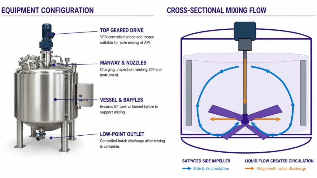
CONTROLLED MIXING CIRCULATION
The top-entry impeller converts drive torque into fluid motion. Internal baffles suppress bulk rotation, allowing useful axial and radial circulation to exchange material between the surface, wall, center and bottom zones.
CONTROLLED BATCH SEQUENCE
PREPARE
Verify cleanliness. valve status, level devices, guards and drive readiness.
CHARGE
Add ingredients under the approved order, rate and minimum mixing level
START
Accelerate under VFD control and confirm stable current, speed and flow.
MIX
Operate for the selected speed, time and product condition window.
VERIFY
Confirm sample. endpoint or uniformity requirement before release
DISCHARGE
Transfer, isolate. clean, inspect and drain the vessel.
CONTROL, SAFETY & MAINTENANCE
Minimum-level permissive
Agitator operation is enabled only above the verified minimum safe liquid level.
Cover and access interlock
The drive is prevented from running when guarded access is open unless a validated safe mode applies.
Drive protection
Motor current, VFD status, speed and optional torque monitoring identify abnormal load.
Process protection
Level, temperature, foaming and overflow conditions are integrated with charging and mixing logic.
Mechanical integrity
Shaft, impeller, seal, bearings and fasteners are selected for operating and upset loads.
Cleaning and inspection
Manway, CIP devices, finish, drainability and removable parts support the cleaning strategy.
PRELIMINARY MIXING TANK GUIDE
This guide supports early screening for atmospheric, non-jacketed, moderate liquid-blending duty. Final working fill, impeller, speed, motor, torque, shaft, seal and blend time require confirmed rheology and mixing objective.
|
MODEL CLASS
|
GROSS VOLUME
|
SCREENING WORKING VOLUME AT 75%
|
LIQUID MASS AT 1.0 kg/L
|
MOTOR RANGE
|
DRIVE CONTROL
|
|---|---|---|---|---|---|
|
AMT-0100
|
100 L
|
75 L
|
75 kg
|
0.37-0.75 kW
|
VFD
|
|
AMT-0250
|
250 L
|
188 L
|
188 kg
|
0.75-1.5 kW
|
VFD
|
|
AMT-0500
|
500 L
|
375 L
|
375 kg
|
1.1-2.2 kW
|
VFD
|
|
AMT-1000
|
1.000 L
|
750 L
|
750 kg
|
1.5-4.0 kw
|
VFD
|
|
AMT-2000
|
2,000 L
|
1,500 L
|
1,500 kg
|
3.0-7.5 kW
|
VFD
|
|
AMT-5000
|
5,000 L
|
3,750 L
|
3,750 kg
|
5.5-15 kW
|
VFD
|
CORE PRELIMINARY CALCULATIONS
1. REQUIRED GROSS VOLUME
Vgross [L] = Required working volume [L]/ selected working fill fraction
2. PRODUCT MASS
Batch mass [kg] = Working volume [L] x operating density [kg/L]
3. SHAFT TORQUE
Torque [N.m] = 9550 x motor power [kW]/agitator speed [rpm]
4. PROCESS POWER BASIS
Motor selection begins from required power per volume, corrected for fluid, impeller, scale and service factor.
FINAL SELECTION CHECKS
Mixing objective
Blend, dissolution, suspension, dispersion and heat transfer require different impeller and power bases.
Rheology and solids
Viscosity curve, density, solids loading, particle size and settling tendency control circulation demand.
Operating levels
Minimum and maximum liquid levels affect submergence, vortexing, shaft loads and mixing time.
Mechanical design
Power, rpm, torque, shaft length, critical speed, seal and impeller loads are verified together.
Controls and safety
VFD, level permissive, cover interlock, overload, temperature and endpoint controls are confirmed.
Hygiene and cleaning
Finish, welds, baffles, impeller, seal, CIP coverage, drain and validation needs are reviewed.
FINAL ENGINEERING CHECK
Confirm bin drawing and mass
Define CV and sampling
Complete representative trial
Verify lift and rotating load
Agree FAT acceptancencriteria
Need the Right AGITATED MIXING TANK
for Your Process?
Our engineers will help you select, size and configure the ideal system for your application.
Download Product Brochure
Fill in your details below to download the brochure.