
STORAGE AND
PROCESS TANK
A hygienic stainless-steel tank for receiving, storing, buffering and transferring liquids or compatible process fluids. The non-agitated design combines closed filling, safe venting, level monitoring, clean access and a low-point sanitary outlet.
HOW THE TANK WORKS

FILL
Receive product through the selected top connection under a free-volume permissive.


VENT
Release displaced air through a clean vent or correctly selected filter.

MONITOR
Track high, low or continuous level and defined holding conditions.

HOLD
Retain product in a closed vessel for storage or process buffering.

TRANSFER
Open the low outlet and deliver by gravity or an external pump.

CLEAN
Wash or clean through the approved method and drain at the lowest point.
APPLICATION FIT & PROCESS VALUE
RIGHT APPLICATION
Pharmaceutical and nutraceutical
Purified liquids, syrups, compatible intermediates and buffer duties under defined hygienic conditions.
Food and beverage processing
Ingredients, water, oils and low-viscosity products requiring closed holding and clean transfer.
Chemical and allied industries
Application-specific storage or day-tank service for compatible process fluids and solutions.
DESIGN VALUE
Reliable buffer capacity
The tank decouples upstream production from downstream demand and stabilizes process scheduling.
Visible inventory
Level indication supports replenishment, transfer control, overflow protection and batch accountability.
Cleanable product path
Top access, selected surface finish and low-point outlet support inspection, cleaning and drainage.
CONSTRUCTION & CONFIGURATION OPTIONS
PRODUCT-CONTACT CONSTRUCTION
SS304 or SS316L with application-specific internal finish, weld treatment and gasket selection.
SHELL AND BOTTOM
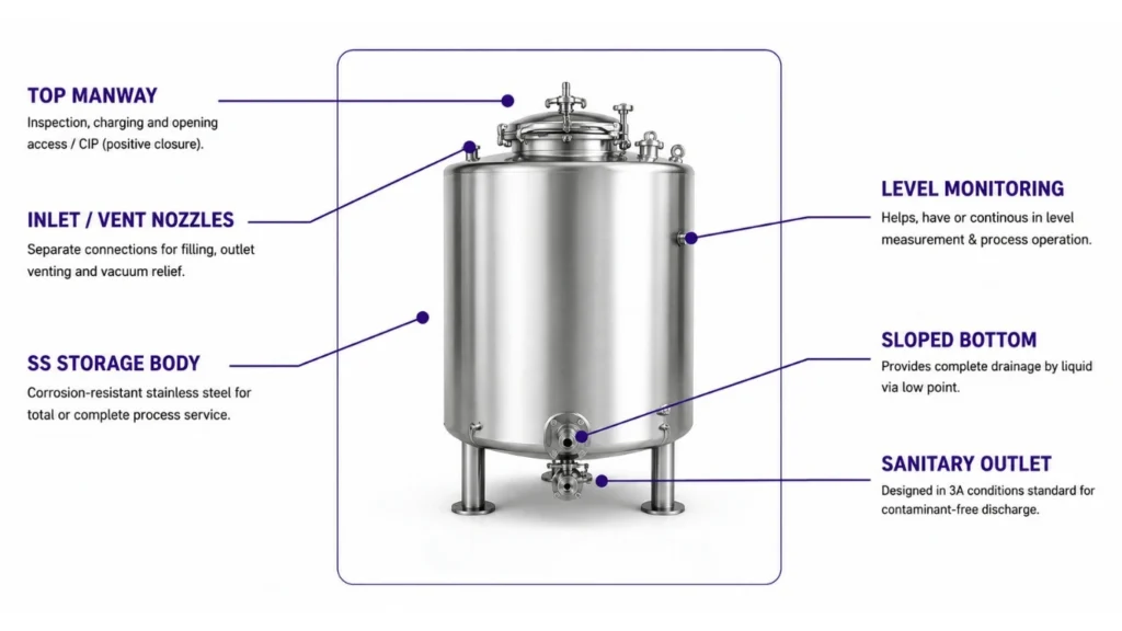
Vertical cylindrical shell with shallow dished, sloped or engineered drainable bottom.
TOP AND ACCESS
Closed top with hinged manway, inlet, vent, CIP and instrumentation connections conr as required.
LEVEL AND PROTECTION
High, low, continuous level, temperature, overflow and pressure/vacuum protection options.
OUTLET AND TRANSFER
Low-point sanitary valve for gravity discharge or connection to an external transfer pump.
SUPPORT AND FINISH
Short legs, skirt or structural support with external finish, insulation and cladding where required.
FILL-TO-DRAIN OPERATING CONCEPТ
Product enters through the selected top inlet while displaced air vents safely. Level instruments protect filling and holding. The batch is retained in a closed tank, transferred through the low outlet and followed by the approved cleaning and drainage cycle.
CONTROLLED OPERATING SEQUENCE
PREPARE
Verify cleanliness, valve status, free volume and vent availability.
FILL
Open the selected inlet under high-level and overflow protection.
VENT
Release displaced air without contamination or tank pressure buildup.
HOLD
Monitor level, temperature and approved residence conditions.
TRANSFER
Prove receiver ready. then open the low outlet or start the pump.
CLEAN
Isolate, wash or clean, inspect and drain from the low point.
CONTROL, SAFETY & MAINTENANCE
Fill permissive
Filling is enabled only with outlet closed, vent available and adequate free volume confirmed.
Overflow protection
Independent high-high level can stop the source and alarm before overfilling.
Pressure protection
Vent and pressure/vacuum protection are selected for fill, drain, pump and cleaning scenarios.
Transfer control
Receiver-ready, valve position and pump permissives establish a controlled product path.
Product condition
Residence time, temperature and material compatibility are monitored against process requirements.
Cleaning and access
Manway, CIP connection, surface finish and low-point drain support the approved cleaning method.
PRELIMINARY TANK CAPACITY GUIDE
This guide supports early capacity screening for atmospheric, non-agitated service. Final freeboard, shell thickness, bottom, support, venting, nozzle
loads and protection require confirmed fluid, operating and site data.
|
MODEL CLASS
|
GROSS VOLUME
|
SCREENING WORKING VOLUME AT 85%
|
LIQUID MASS AT 1.0 kg/L
|
OUTLET RANGE
|
SUPPORT BASIS
|
|---|---|---|---|---|---|
|
SPT-0500
|
500 L
|
425 L
|
425 kg
|
DN25-DN50
|
Legs
|
|
SPT-1000
|
1,000 L
|
850 L
|
850 kg
|
DN40-DN65
|
Legs
|
|
SPT-2000
|
2,000 L
|
1,700 L
|
1,700 kg
|
DN40-DN80
|
Legs /skirt
|
|
SPT-5000
|
5.000 L
|
4,250 L
|
4,250 kg
|
DN50-DN100
|
Engineered
|
|
SPT-10000
|
10,000 L
|
8,500 L
|
8,500 kg
|
Engineered
|
Engineered
|
|
SPT-20000
|
20,000 L
|
17,000 L
|
17,000 kg
|
Engineered
|
Engineered
|
CORE PRELIMINARY CALCULATIONS
1. REQUIRED GROSS VOLUME
Vgross [L] = Required working volume [L]/ selected working fill fraction
2. LIQUID HOLDING MASS
Liquid mass [kg] = Working volume [L] x operating density [kg/L]
3. HOLDING TIME
Residence time [h] = Available working volume [L]/ average process demand [L/h]
4. MAXIMUM SUPPORT LOAD
Design basis includes tank tare + maximum liquid + fittings + piping loads + dynamic and site loads.
FINAL SELECTION CHECKS
Fluid properties
Density, viscosity, solids, pH, corrosion, temperature and compatibility
determine construction.
Freeboard and venting
Fill rate, surge, foaming, thermal expansion and pump-out conditions define volume and vent duty.
Drainability
Bottom geometry, outlet position, viscosity and floor elevation determine residual hold-up and transfer.
Pressure protection
Normal and abnormal fill, drain, pump and cleaning cases define vent and protection requirements.
Structure and site
Tare, maximum liquid, nozzle, piping, wind, seismic, access and floor loads are verified.
Hygiene and cleaning
Finish, welds, gasket, manway, CIP coverage, drain and validation needs are application-specific.
Need the Right STORAGE AND PROCESS TANK
for Your Process?
Our engineers will help you select, size and configure the ideal system for your application.
Download Product Brochure
Fill in your details below to download the brochure.